Sep 14, 2026Services Overview
WJ Worm Gear Reducer for Boiler Applications: Structure, Features and Selection Guide
WJ worm gear reducer for boiler grate, fuel feeding and ash removal systems. Compact design, high reduction ratio, smooth operation and reliable torque transmission.
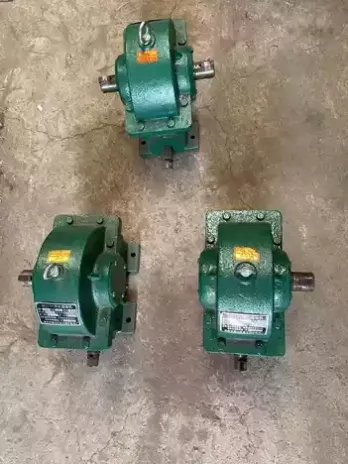
In industrial boiler systems, reliable power transmission is essential for stable and continuous operation. Equipment such as grate drives, fuel feeding systems, ash removal systems, and conveyors often require a compact and reliable gearbox to reduce motor speed and increase output torque.
The WJ worm gear reducer is one type of gearbox that can be used for these applications. Its compact structure, high reduction ratio, smooth transmission, and convenient installation make it suitable for various boiler auxiliary drive systems.
What Is a WJ Worm Gear Reducer?
The WJ series is a worm gear speed reducer designed to transmit power through a worm and worm wheel mechanism.
The motor provides high-speed input, while the worm gear mechanism reduces the speed and increases the output torque required by the driven equipment.
Typical features of a WJ worm gear reducer include:
- Compact and relatively lightweight construction
- High reduction ratios
- Smooth and quiet operation
- High output torque
- Hollow output shaft options
- Flexible installation arrangements
- Easy connection with electric motors
- Suitable for low-speed, high-torque applications
The hollow output shaft design can also simplify the connection between the reducer and the driven shaft in certain boiler applications.
Where Can a WJ Reducer Be Used in a Boiler System?
A boiler normally contains several mechanical systems that require controlled and continuous movement. Depending on the equipment design, a WJ reducer can be considered for applications such as:
- Boiler Grate Drive
For solid-fuel and biomass boilers, the grate needs to move fuel through the combustion chamber at a controlled speed.
The WJ reducer can reduce the motor speed and provide the torque required to drive the grate mechanism.
A stable output speed is important because excessive grate speed may affect combustion efficiency, while insufficient speed can cause fuel accumulation.
- Fuel Feeding System
-
Coal, biomass, wood chips, pellets, and other fuels may be transported into the combustion chamber by screw conveyors, chain conveyors, or other feeding mechanisms.
These systems usually operate at relatively low speeds and require sufficient starting torque.
A WJ worm gear reducer can be used between the motor and the feeding mechanism to provide the required speed and torque.
- Ash Removal System
Boiler ash removal equipment may use conveyors, screw systems, chains, or other mechanical mechanisms.
Because these systems often operate continuously and under dusty conditions, the reducer needs to provide stable torque transmission and reliable operation.
- Conveyor Drive
Boiler rooms and fuel handling systems may include belt conveyors, chain conveyors, or other material-handling equipment.
The WJ reducer can be used to reduce motor speed and drive these conveyors at the required operating speed.
Why Use a Worm Gear Reducer for Boiler Equipment?
Boiler auxiliary equipment generally does not require extremely high output speeds. Instead, it often needs:
- Low output speed
- High reduction ratio
- Sufficient starting torque
- Stable continuous operation
- Compact installation dimensions
- Simple mechanical connection
These requirements are well suited to the characteristics of a worm gear reducer.
For example, a standard electric motor may operate at approximately 1,500 rpm, while a grate or conveyor may need to operate at only several tens of rpm.
The gearbox therefore needs to provide a substantial speed reduction while increasing the available output torque.
Important Factors When Selecting a WJ Reducer
Choosing a suitable WJ worm gear reducer should not be based only on the reduction ratio.
Several operating parameters should be considered.
Motor Power
The first parameter is the motor power.
For example:
0.75 kW
1.5 kW
2.2 kW
3 kW
4 kW
5.5 kW
The actual required power depends on the driven equipment and operating conditions.
Input Speed
Common industrial motors operate at approximately 1,450–1,500 rpm for 4-pole motors at 50 Hz.
However, the actual input speed should be confirmed before selecting the reducer.
Output Speed
The required output speed depends on the boiler equipment.
For example, a grate drive may require a very low output speed, while a fuel conveyor may require a somewhat higher speed.
The approximate relationship is:
Output Speed = Input Speed ÷ Reduction Ratio
For example, with an input speed of 1,500 rpm and a reduction ratio of 30:1:
1,500 ÷ 30 = 50 rpm
The actual output speed may vary depending on the motor speed and gearbox specifications.
Output Torque
Torque is particularly important for boiler applications.
The gearbox must provide enough output torque to overcome:
- Starting resistance
- Material load
- Friction
- Mechanical transmission losses
- Shock loads
- Continuous operating loads
For equipment with frequent starts and stops or heavy starting loads, an appropriate service factor should be considered.
Boiler Operating Environment
The working environment should also be considered when selecting a gearbox.
Boiler systems may involve:
High ambient temperatures
Dust
Ash
Vibrations
Continuous operation
Frequent starting and stopping
Heavy or impact loads
The reducer should therefore be installed in a suitable position with adequate ventilation and protection.
If the gearbox is installed close to a high-temperature area, additional attention should be paid to operating temperature, lubrication, seals, and cooling conditions.
Installation Considerations
The actual installation position depends on the boiler equipment structure.
Before ordering a WJ reducer, it is recommended to confirm:
Motor power
Motor speed
Required reduction ratio
Required output speed
Required output torque
Output shaft diameter
Input shaft or motor connection
Mounting position
Operating hours per day
Load characteristics
Ambient temperature
Whether shock or impact loads are present
Correct installation is particularly important for grate and conveyor drives because misalignment between the gearbox and driven shaft can increase bearing and shaft loads.
Lubrication and Maintenance
Worm gear reducers require appropriate lubrication to maintain efficient and stable operation.
Before commissioning the gearbox, check the lubricant level according to the manufacturer's instructions.
During operation, regularly inspect:
Oil level
Oil leakage
Housing temperature
Shaft seals
Mounting bolts
Output shaft connection
Abnormal noise or vibration
If the reducer operates continuously under heavy loads or high temperatures, a shorter inspection interval may be appropriate.
WJ Worm Gear Reducer vs. Other Gearbox Types
A worm gear reducer is not always the best solution for every boiler application.
For applications requiring very high efficiency, high continuous output torque, or heavy-duty operation, a helical, bevel-helical, or planetary gearbox may be a better choice.
A worm gearbox can be attractive when the application prioritizes:
Compact dimensions
High reduction ratio
Smooth operation
Simple installation
Cost-effective transmission
The final selection should therefore be based on the actual load, speed, torque, duty cycle, and installation requirements.
How to Choose the Right WJ Reducer for a Boiler
A practical selection process can be summarized as follows:
Motor → Input Speed → Required Output Speed → Reduction Ratio → Output Torque → Load Type → Service Factor → Installation Position
For example:
A boiler grate uses a 2.2 kW motor running at approximately 1,500 rpm. If the required grate speed is around 50 rpm, the theoretical reduction ratio is approximately:
1,500 ÷ 50 = 30:1
The next step is to verify whether the selected WJ model can provide sufficient output torque for the actual grate load and starting conditions.
Therefore, the reduction ratio alone is not enough to determine the correct gearbox size.
Conclusion
The WJ worm gear reducer can be a practical transmission solution for various boiler auxiliary systems, including grate drives, fuel feeding equipment, ash removal systems, and conveyors.
Its compact design, high reduction ratio, smooth operation, and convenient installation make it suitable for many low-speed and high-torque applications.
However, gearbox selection should always be based on the complete operating conditions rather than simply choosing a model according to motor power or reduction ratio.
For a proper WJ reducer selection, the key information should include motor power, input speed, required output speed, load torque, duty cycle, mounting position, shaft dimensions, and operating environment.